Paul March provides updates on the EMdrive and Cannae drive experiments at Eagleworks NASA.
Read more »![]()
If one envisions the quantum vacuum (Q-V) as a semi-virtual electrical plasma as Dr. White does, that would imply that the Poynting power flow vector would entrain the Q-V plasma and send it on its way toward the pillbox end of the cavity and then out of the cavity, the back-reaction on the cavity should be in the opposite direction towards the RF feed end of the Cannae test article, but the observed thrust vector is opposite to that surmise, i.e. toward the shorter RF sense antenna end of the cavity per the attached slide.
Now Per the newly authored Q-V plasma simulation code that Dr. White just finished, the equal bidirectional Q-V plasma flow for the Cannae cavity comes from the high-Q pancake section with a Q of ~9,000 for the un-slotted version of the cavity. However due to the high E-field region created n the throat of the RF feed, this cylindrically shaped high E-field volume acts as an obstruction to the Q-V plasma flow. This E-field obstruction created in the PTFE cylinder then accelerates the Q-V plasma around it in a Bernoulli like effect that accelerates the Q-V plasma flow coming from the main pillbox cavity. This unbalanced and accelerated Q-V plasma flow that goes away from the large pill box cavity in the direction of the RF input section is what generates the NET thrust in our model.
Next, using this new Q-V plasma simulation tool that utilizes the instantaneous E&M fields from COMSOL for one complete RF cycle in 5 degree increments as its input file, we are now seeing why we need the PTFE or HDPE dielectrics in the frustum while using near pure sine wave power levels below ~100W in the ~2.0 GHz frequency range to generate detectable thrust, and why Shawyer and the Chinese didn't while pumping 80W to 2,500W using magnetron RF sources. We think the reasons are two fold.
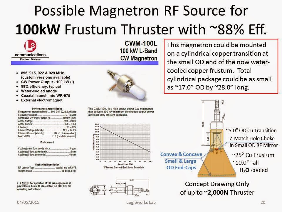
The first is that Shawyer and the Chinese both used magnetron RF sources for their experiments. An RF source that generates large AM, FM and PM modulation of the carrier wave with typical FM modulation bandwidth on the order of at least +/-20 MHz. (These time rate to change of energy modulations increase the Q-V density in our model.)
The second reason we found running these 3D Q-V plasma simulations for the EMPTY copper frustum, was that increasing the input power tends to focus the Q-V plasma flow from near omnidirectional from the frustum at low powers, to a much more jet like beam at higher powers measured in kW to tens of kW-rf. In fact the simulation for the 100W run predicted only ~50uN for our pure RF system with dielectric, while the 10kW run predicted a thrust level of ~6.0 Newton without a dielectric in the cavity. And at 100kW-rf it was now up to ~1300 Newton, but the input power to thrust production nonlinearity was starting to taper off around 50kW. Of course these Q-V plasma thrust predictions are based on the Q-V not being immutable and non-degradable, a feature we admit is not widely accepted by the mainstream physics community, at least at the moment.
Due to the above non-linear thrust scaling with input power predictions, we have started the build up of a 100W-to-1,200W waveguide magnetron RF power system that will drive one of our aluminum RF frustum cavities. Initially the test rig will follow Shawyer's first generation test rig that used a tetter-totter balance system in air only to see if we can generate similar thrust levels that Shawyer reported using a hermetic sealed box, which were in the ~16 to 300 milli-Newton range dependent on the Q-Factor of the frustum.
Read more »


